Composite Shear Tests
Various test methods are established for determining the shear strength. These differ in the type of load application (as a compressive load via the specimen edge or as a frictional load via the clamping jaw systems) or in the geometry of the specimens (unnotched, notched, miniaturised). In addition, the widely used tensile test can be converted into a shear test through fibre orientation in the +/-45° direction and statements about the shear strength can be determined from the bending test. All established methods have in common that they can only be used to obtain reliable results for low shear deformations (< 5 %) and thus only for low shear loads.
However, the reliable characterisation of high-performance fibre composites is becoming increasingly important. We have specialised in this field and, in addition to the established test methods, we offer you the shear test according to DIN EN ISO 20337 (formerly DIN SPEC 4885), an innovative test method that we developed together with the Federal Institute for Materials Research and Testing. With this test method, significantly higher shear loads and thus higher strengths can be tested than before.
- Test method for orthotropic FRP (GFK, CFK, ...) for determining the shear properties (shear properties within the layer plane)
- Specimen geometry 250 mm x 25 mm x 2 mm with fiber orientation in +/- 45 ° direction
- Application of an adapted DMS rosette in 0° / 90° orientation
- Determination of shear strength, shear stiffness and shear stress-strain curve
In accordance with DIN EN ISO 14129 (or ASTM D3518) shear characteristics are determined in the tensile shear test on flat test specimens with a fiber orientation in a +/- 45° direction. The test specimen is ideally symmetrical and balanced from its laminate construction and consists of a fabric or a biaxial scrim. The characteristic value determination is carried out quasi-statically as a tensile test. The test method has the following disadvantages compared to other methods:
- The test is not applicable to the determination of fracture toughness for materials with high shear strain, as the process is limited to shear deformations < 5 %.
- The resulting stress state in the test specimen is multiaxial. In the single layer of the specimen both normal and shear stresses are present. The fiber-perpendicular stresses generate additional ZFB stress in the laminate and thus an influence on the shear characteristics. The determination of the shear strength according to DIN EN ISO 14129 is therefore not possible error-free due to the principle.
- The free (not clamped) edges of the specimen lead to load transfer effects.
- It is assumed that the load is inhomogeneous over the width of the specimen.
The advantage of the test method over other methods for determining shear rate value lies in the simplicity of the test procedure. It is essentially a tensile test which has been modified by the fiber orientation in the +/- 45° direction for the determination of the shear characteristics.
- Test method for anisotropic and orthotropic FRP (GFK, CFK, ...) and isotropic plastics (pure resin, adhesive resin, plastic, etc.) for determining the shear properties (shear properties within the layer plane)
- Testing by a picture frame test fixture (eg GZ S-100 / S-100 HT)
- Test specimen geometry 165 mm x 165 mm x 2...4 mm, possibly with fiber orientation in 0 ° or 0 ° / 90 ° direction or multi-directional design
- Application of two adapted strain gauges in 45° orientation
- Determination of shear strength, shear stiffness and shear stress-strain curve
- Approval according to DNVGL-guideline ST-0376 ("Rotor Blades for Wind Turbines") for the certification of rotor blades of wind turbines
The picture frame shear test according to DIN EN ISO 20337 / DIN SPEC 4885 is carried out by means of a picture frame. The test method is applicable to laminates consisting of a thermoplastic or thermosetting matrix and having fiber orientations in the 0° and 0° / 90° directions, respectively. The test specimens with a square basic shape are symmetrical and balanced around the median plane. Typical specimen thicknesses are in the range 2...4 mm. The material costs and the requirements of the test apparatus are higher than in other shear test methods, but there are significant advantages of this test method:
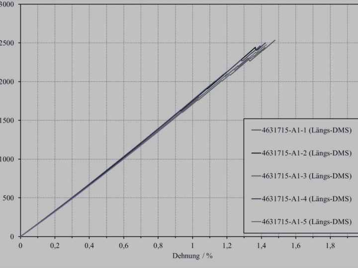
- The determination of the shear properties can take place both in the linear and in the non-linear load-deformation range with shear strains > 5 %. Thus, a determination of the maximum shear strength in this strain range is possible, which is not possible with any other shear test.
- Due to the surface clamping of the specimen there are no free edges, so that no load transfer effects occur.
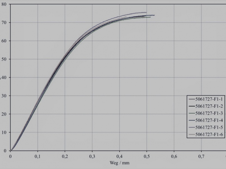
- The test results show very low standard deviations (usually < 3 %). Thus, the test method is also suitable for parameter studies or production that accompanies quality assurance (eg. incoming goods inspection).
- In the single layer of the specimen, only pure shear stresses are present. The stress is distributed relatively homogeneously over the sample. The shear stress maximum is in the test center, so that the failure of the specimen is observed.
- Test method for orthotropic FRP (GFK, CFK, ...) for determining the thrust properties (thrust properties within the layer plane)
- Specimen geometry 250 mm x 25 mm x 2.5 mm with fiber orientation in +/-45° direction
- Application of an adapted DMS rosette in 0°/90° orientation
- Determination of shear strength, shear stiffness and shear stress-strain curve
In accordance with ASTM D3518 (or DIN EN ISO 14129) shear characteristics are determined in the so-called tensile shear test on flat test specimens with a fiber orientation in a +/-45 ° direction. The test specimen is ideally symmetrical and balanced from its laminate construction and consists of a fabric or a biaxial scrim. The characteristic value determination is carried out quasi-statically as a tensile test. The test method has the following disadvantages compared to other methods:
- The test is not applicable to the determination of fracture toughness for materials with high shear strain, as the process is limited to shear deformations < 5 %.
- The resulting stress state in the test specimen is multiaxial. In the single layer of the specimen both normal and shear stresses are present. The fiber-perpendicular stresses generate additional ZFB stress in the laminate and thus an influence on the shear characteristics. The determination of the shear strength according to ASTM D3518 is therefore not possible error-free due to the principle.
- The free (not clamped) edges of the specimen lead to load transfer effects.
- It is assumed that the load is inhomogeneous over the width of the specimen.
The advantage of the test method over other methods for determining shear rate value lies in the simplicity of the test procedure. It is essentially a tensile test which has been modified by the fiber orientation in the +/-45° direction for the determination of the shear characteristics.
- Test method for anisotropic and orthotropic FRP (GFK, CFK, ...) and isotropic plastics (pure resin, adhesive resin, plastic, ...) for determining the shear properties (shear properties within the layer plane)
- Testing with Iosipescu test fixture (eg GZ IS-20 )
- Test specimen geometry 76 mm x 19 mm x 2 mm, possibly with fiber orientation in 0° or 90° or 0°/90° direction or multi-directional design
- Application of an adapted DMS rosette in +/-45° orientation
- Determination of shear strength, shear stiffness and shear stress-strain curve
In the Iosipescu shear test, shear characteristic values of asymmetrically loaded four-point bending specimens are determined in accordance with ASTM D5379. The specimen is clamped by a Iosipescu device, which consists of two relatively movable profiles. The loads are conducted over four areas in the test specimen. A V-notch of the specimen determines the location of the failure. The material stress in the specimen represents a transverse force shear stress. The test method has the following disadvantages compared to other methods.
- The test is not applicable to the determination of fracture toughness for materials with high shear strain, as the process is limited to shear deformations < 5 %.
- The method is intended for small material deformations. Large deformations lead to load transfers in the fiber direction with horizontally oriented fibers (fiber orientation in the 90° direction).
- The shear stresses in the center of the test specimen deviate significantly from the mean shear stress. The deviation is about 20 % for fiber orientation in the 90 ° direction and about 10 % for the fiber orientation in the 0° direction. Therefore, there is no homogeneous shear stress distribution in the specimen cross section.
- The production of the V-notch of the specimen causes a failure of the specimen at different loads due to a varying stress situation in the notch.
- In the load introduction area, the compressive strength of the material can be exceeded, which may lead to a crushing of the edge of the specimen.
The advantage of the test method over other methods for determining shear rate value lies in the simplicity and flexibility of the test procedure. Single and multi-axially oriented laminates with any fiber orientation can be tested with just one test method.
- Test method for anisotropic and orthotropic FRP (GFK, CFK, ...) for determining the shear properties (shear properties within the layer plane)
- Testing by a rail shear test fixture (eg GZ RS-50 / RS-50 H)
- Test specimen geometry 76 mm x 56 mm x 2 mm, possibly with fiber orientation in 0° or 0°/90° direction
- Application of an adapted DMS rosette in +/-45° orientation
- Determination of shear strength, shear stiffness and shear stress-strain curve
The rail shear test according to ASTM D7078 (or ASTM D4255) uses a test specimen, which is clamped on both sides between two opposing device halves via clamping jaws. The tensile force generated by the universal testing machine causes a shear stress in the test specimen via the device. The test method has the following disadvantages compared to other methods:
- The method is intended for small material deformations. Large deformations lead to load transfers in the fiber direction with horizontally oriented fibers.
- The state of shear stress in the specimen is not completely homogeneous and extends parabolically over the width of the specimen.
- The V-notch results in a critical state of stress in the specimen which is heavily dependent on the production.
The advantage of the test method over other methods for determining shear rate value lies in the simplicity of the test procedure.


